
ACI Multi-Pod Deployment
- Mukesh Chanderia

- May 16, 2024
- 7 min read
Updated: Feb 18

Each POD has local instance of ISIS and COOP
Inter-POD connectivity is through IPN
Inter-POD BUM uses PIM-Bidir
BGP in between PODs to share endpoints and external routes.
Multipod Overview
Why Multipod?
Traditional ACI can be stretched across multiple sites, but it becomes less scalable if every spine has to extend all protocols (ISIS, COOP, BGP) across large distances.
Multipod addresses the scalability challenge by segmenting the fabric into distinct “pods,” each with its own local instance of ISIS and COOP, interconnected via an IP network (IPN).
Key Multipod Concepts
Separate Pods: Each pod runs its own COOP and ISIS processes.
IPN (Inter-Pod Network): External routing domain (often dedicated WAN/Layer 3 network) that interconnects pods. Must support OSPF, jumbo MTU (9150 bytes), PIM bidir for multicast, and DHCP relay.
MP-BGP: Spines exchange endpoint and external-route information via BGP EVPN or VPNv4 across the IPN.
APIC Cluster
All APICs form a single cluster across pods.
The “seed” pod typically hosts the initial APIC(s). APICs in other pods join the same cluster by referencing the seed pod configuration
Configuration Steps :
Step 1
IPN-X# show lldp neighbors

Step 2
On the IPN, configure the following items for OSPF connectivity to the spine in the seed pod:
VLAN 4. This VLAN ID is a fixed ID used by the configuration wizard in the APIC user interface to establish IPN connectivity.
VRF interpod. Although not mandatory for inter-pod (IPN) communication, it is recommended for traffic segregation.
OSPF process interpod-ospf. The VRF and OSPF process names have only local significance.
MTU 9150 on Ethernet 1/49. This MTU is a default value configured by the wizard in the APIC user interface. Eth1/49 is connected to the spine.
Routed subinterface Eth1/49.4 for VLAN ID 4 with these parameters:
MTU 9150
Member of VRF interpod.
IP address 172.16.1.22/30
Member of the OSPF backbone area
IPN-x(config)# vlan 4 vrf context interpod router ospf interpod-ospf vrf interpod interface Ethernet1/49 mtu 9150 no shutdown interface Ethernet1/49.4 encapsulation dot1q 4 mtu 9150 vrf member interpod ip address 172.16.1.22/30 ip router ospf interpod-ospf area 0.0.0.0 no shutdown
Step 3
On IPN, enable OSPF connectivity to the second pod spine using the following parameters:
MTU 9150 on Ethernet 1/50.
Routed subinterface Eth1/50.4 for VLAN ID 4 with these parameters:
MTU 9150
Member of VRF interpod
IP address 172.16.1.26/30
Member of the OSPF process interpod-ospf and backbone area
interface Ethernet1/50 mtu 9150 no shutdown interface Ethernet1/50.4 encapsulation dot1q 4 mtu 9150 vrf member interpod ip address 172.16.1.26/30 ip router ospf interpod-ospf area 0.0.0.0 no shutdown
Note: This OSPF configuration is not related to the seed pod, but it is required to enable DHCP exchange between the second pod and the APIC in the seed pod.
Step 4
Go to Fabric > Inventory > Quick Start > Add Pod and choose Add Pod.


Step 5
Read the information about interpod (IPN) connectivity requirements and click Get Started.

Step 6
In IP Connectivity, enter the following parameters and click Next:
Spine ID: 201
Interface: 1/32 (spine interface connected to IPN)
IP address: 172.16.1.21/30
MTU (bytes): 9150

These parameters define the IP settings of the peer link to the IPN.
Step 7
In Routing Protocol, choose the interface policy default and click Next.

Instead of using the default policy, which is defined within tenant common, and uses default OSPF timers and parameters, you may configure a custom policy with point-to-point network type. In that case you would need to configure the point-to-point network type on the IPN switch.
Step 8
In External TEP, configure the following values and click Next:
External TEP Pool: 192.168.1.0/24 (Keep the default auto-filled value). Caution - if you enter this address instead of keeping the auto-filled value, the wizard will return an error and you will have to repeat the procedure. Leave the auto-filled address unchanged.
Data Plane TEP IP: 192.168.90.1/32 (BGP next-hop for networks advertised by the seed pod to other pods)
Router ID: 10.4.4.4


The data plane TEP IP is the BGP next-hop for endpoints in the seed pod advertised to other pods. It must be routable across all locations.
You will find above multipod configuration at

Step 9: Review the objects that will be created by the wizard and click Finish.


You will need to refresh the browser to connect to the APIC.
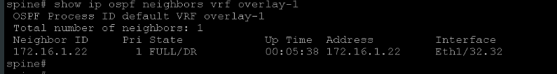
Step 10: On IPN and, optionally, spine, verify the OSPF adjacency after a short while.

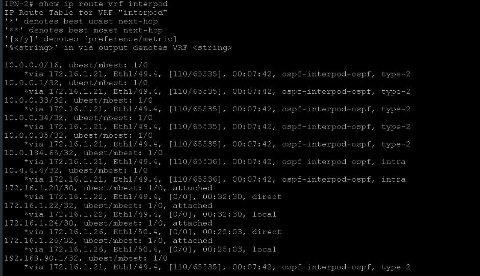
Step 11: On IPN, examine the routing table for the multi-pod VRF.
Step 12: In the APIC user interface, close the Add Physical Pod window and go to Fabric > Inventory > Fabric Membership > Nodes Pending Registration

You may expect the pod-2 spine, as it should request an IP address via DHCP. Should the IPN be configured to forward the DHCP requests to the APIC? Which interface should be used as the DHCP relay interface?
Step 13: On IPN, enable the DHCP feature. On the pod-2 facing sub interface Eth1/50.4, configure DHCP relay toward the APIC IP address (10.0.0.1).

The DHCP relay must be configured on the routed subinterface toward pod-2, even though the pod-2 spine does not yet have any configuration. After discovering an LLDP neighbor, the spine starts sending DHCP requests tagged with VLAN 4. The DHCP requests are broadcast packets. The IPN must relay them to the APIC address as unicast traffic sourced from the incoming interface.
Step 14: In the APIC user interface, re-examine the Nodes Pending Registration.

The spine from pod 2 is pending registration. The APIC has received its DHCP requests. You will register it after configuring the second pod.
Step 15: On IPN, ping the APIC.

Step 16: Examine L3Out in the Seed Pod

Step 17: Expand the L3Out configuration and examine its sub-elements, including the logical interface profile

The L3Out establishes the OSPF adjacency over a routed subinterface with VLAN ID 4. You have configured a subinterface with the same VLAN ID on the IPN.
External EGP

Step 18: Go to Fabric > Access Policies > Physical and External Domains > L3 Domains and examine multipodL3Out_RoutedDomain.

The L3 domain is associated with three automatically provisioned objects: two AAEPs (multipodL3Out_EntityProfile, Spine201_EntityProfile), and a VLAN pool.
Step 19: Go to Fabric > Access Policies > Pools > VLAN and examine the VLAN pool multipodL3Out_VlanPool.

Spine uses sub-interfaces, which do not require a VLAN pool. This configuration is not strictly needed.
Step 20: Go to Fabric > Access Policies > Interfaces > Spine Interfaces > Policy Groups


Step 21: Go to Fabric > Inventory > Pod 1 > spine (Node-201) > Protocols > OSPF, expand the menu and examine the OSPF information in the General tab, and the OSPF adjacency in the Neighbors tab.


Within the spine, go to Interfaces > Physical Interfaces > eth1/32 and examine the interface parameters, including the information in the Deployed EPGs tab

Add Second Pod
Step 22: Go to Fabric > Inventory > Quick Start > Add Pod and choose Add Pod.
In the Pod Fabric page, enter the following parameters and click Next:
Pod ID: 2
Pod TEP Pool: 10.2.0.0/16. The TEP pool must be unique for each pod. This range differs from the TEP pool of pod 1 (10.0.0.0/16).
Spine ID: 2201. This ID belongs to the spine in the second pod. It will be attached to the IPN by adding a logical node profile to the provisioned L3Out.
Interface: 1/1. This is the interface on pod-2 spine that is connected to the IPN. A logical interface profile will be added to bring in this connection to the L3Out.
IPv4 Address: 172.16.1.25/30. This IP address belongs to the pod-2 spine on the IPN-facing link.
MTU (bytes): 9150


Step 23: In the External TEP page, enter the following parameters and click Next:
Data Plane TEP IP for the second pod: 192.168.90.2/32
Router ID for node 2201: 10.5.5.5


Step 24: Go to the infra tenant, expand the L3Out configuration, and examine its newly added sub-elements, the logical node profile, and logical interface profile.

You cannot verify OSPF connectivity between the IPN and the second pod because the pod-2 spine has not yet been discovered and registered.
Step 25: Within the infra tenant, go to Policies > Protocol > Fabric Ext Connection Policies > Fabric Ext Connection Policy default and examine the available profiles.

Step 26: Register Spine POD2

Step 27: set OOB ip address
Go to the mgmt tenant and choose Node Management Addresses > Static Node Management Addresses. Configure the spine-pod2 OOB management address with the following settings. Then click Submit and Yes.
Node Range: From: 2201 To: 2201
Config: Choose Out-Of-Band Addresses
Out-Of-Band management EPG: default
Out-Of-Band IPv4 address: 192.168.10.214/24
Out-Of-Band IPv4 gateway: 192.168.10.254
Step 28 : connect via SSH to the APIC (by name apic). Log on as admin with password. Examine lines that contain 'bootstrap' in /var/log/dme/log/access.log.

POD2 spine must have default path towards IPN for overlay-1.

TSHOOT
Issue : Pod2 Spines Don’t Receive L3out IP or Config
Possible Causes
1. DHCP Relays on IPN point to APIC OOB rather than infra
✓Configure Relays to point to infra (show controller on APICs)
2. IPN doesn’t have route to APICs
✓Check that OSPF is up between IPN and Pod1
3. Miscabling results in Spine receiving IP in different subnet than GW
✓Correct cabling or addressing then remove and rediscover Spine
4. Spines can’t resolve ARP for connected IPN interface
✓Ensure SW version supports multipod + spine hw (ex: for 9364C MPOD
supported in 3.1(1))
Issue : Pod2 Spines Don’t Receive TEP Addresses
Ensure leafs are connected to spine
-Spine TEP not assigned until leaf-facing interfaces “up”
Issue: Remote Pod APIC Not Joining Cluster
Check sam file and ensure config is correct.
ftriage Command
In ACI 4.2 and later, ftriage helps trace packet paths across leaves/spines, showing each step of forwarding logic.
apic1# ftriage route -ii LEAF:101,103 -dip 172.16.2.3 -sip 172.16.1.1
What the Command Does
ftriage route
ftriage is a Cisco ACI troubleshooting utility (introduced in ACI 4.2 and later) that can trace packet flow end to end.
The route option instructs ftriage to analyze a routed (layer 3) flow.
-ii LEAF:101,103
-ii means “ingress interfaces” (or ingress leaf switches) to begin the trace.
By specifying LEAF:101,103, you’re telling ftriage to look for traffic ingressing leaf 101 or leaf 103. If ftriage sees the flow on either of these leaves, it captures information there and follows the packet along its path through the fabric.
-dip 172.16.2.3 -sip 172.16.1.1
-dip is the destination IP of the flow (i.e., 172.16.2.3).
-sip is the source IP of the flow (i.e., 172.16.1.1).
• • With this, ftriage will look for traffic where 172.16.1.1 is sending packets to 172.16.2.3.


Comments