
ACI Vmware DVS
- Mukesh Chanderia

- Apr 22, 2024
- 24 min read
Updated: 15 hours ago
APIC integrates with 3rd party VMMs
Three options with Virtual VMM:
VMware DVS
Cisco ACI Virtual Edge
Cisco Application Virtual Switch (It's now End of Life)
Ensure VMware and ACI version support.
Note : Linux Commands to check ip and Gateway
Ip addr
Ip route show
Vmware Settings You should not change

VMM Domain Integration with ACI
Step 1: Create pool for VMM domain
Fabric > Access Policies > Pools. Right-click VLAN and choose Create VLAN Pool.

In the Range field, enter values 100 and 199. Click OK.

Step 2: Create vCenter Domain
Go to Virtual Networking > VMware. Right-click VMware and choose Create vCenter Domain

In the Virtual Switch Name field, enter vCenter_VMM. In the Virtual Switch field, choose the VMware vSphere Distributed Switch option. From the VLAN Pool drop-down menu, choose vCenter_VLANs.

Note: We have not yet attached AAEP profile.
Now scroll down and configure Port Channel - Mode On & select CDP.

Step 3: Expand the VMM domain, right-click Controllers, and choose Create vCenter Credential.

Step 4: Set the Credential

Step 5: LAUNCH VSPHERE CLIENT (HTML5). Log in to the vSphere web client as administrator@dc.local
In the vSphere Web Client, go to Networking, expand the data center DC, and verify that no VDS exists.

You should not see a VDS because you still need to complete the VMM domain configuration on the APIC. Therefore, the VDS still needs to be pushed to the vCenter.
Step 6: In the APIC GUI, in the Controllers menu, choose Create vCenter Controller.

Note: The name of Datacenter must be exactly the same as been configured in vSphere.
Step 7: Verify the VDS that the APIC has pushed.

You should see a VDS with the name of the configured vCenter domain (vCenter_VMM) within a folder of the same name. The VDS includes two networks that have been automatically created.
Step 8: Verify that CDP has been enabled on this VDS in both directions

Step 9: In the APIC UI, create a new AAEP.
Fabric > Access Policies > Policies > Global, right-click Attachable Access Entity Profiles, and choose Create Attachable Access Entity Profile.


Step 10: Associate HOST_AAEP AAEP to your VPC policy group Leaf101..102:1:03_VPCIPG and save the configuration.

Step 11: Associate VMM Domain to App_EPG
Application Profiles > eCommerce_AP > Application EPGs. Right-click the App_EPG and choose Add VMM Domain Association.

VMM Domain Profile drop-down menu, select vCenter_VMM and click Submit
Step 12: In DB_EPG and Web_EPG, use the same method to associate the EPGs with your VMM domain.
Step 13: In the vSphere client, within the VDS vCenter_VMM examine the port groups.
Examine the port groups by expanding the VDS or in the Networks tab. Refresh the browser if needed.

Step 14: Add ESXi Host to the VDS (Optional)
In the vSphere Web Client, go to Networking. Right-click the created VDS and choose Add and Manage Hosts.


Note : There is alternate way to configure Vmware Host in ACI as well
Step 15: Select your host to be added to the distributed switch.

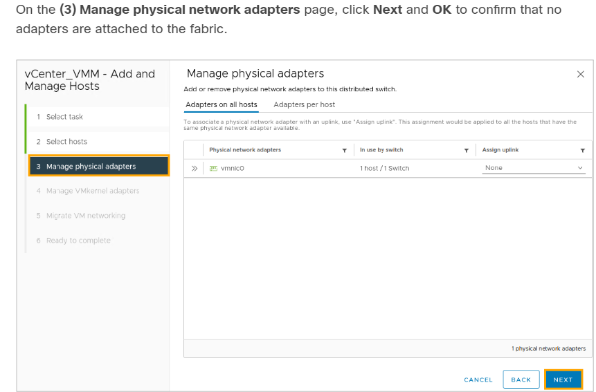
Step 16: Don’t add any physical adapters. In this scenario, there is no hardware fabric.

Step 17 : Confirm that the host has no physical network adapters attached to the fabric.

Step 18 : Do NOT assign any VMkernel network adapters to the distributed switch

Step 19 : Do not migrate any virtual machines or network adapters to the distributed switch.

Step 20: On the (6) Ready to complete page, click Finish.

Step 21: In the vSphere Web Client, manage a host added to your new VDS.

Step 22: On the (1) Select task page, select Manage host networking and click Next.

Step 23: On the (2) Select hosts page, select your ESXi (10.10.1.1). Click Next.

Step 24: Do not add any physical adapters.
Step 25: Do not assign any VMkernel network adapters to the distributed switch.

Step 26 : Perform these assignments:
APP_VM to Sales|eCommerce_APP|App_EPG
DB_VM to Sales|eCommerce_APP|DB_EPG
WEB_VM to Sales|eCommerce_APP|Web_EPG
On the (5) Migrate VM networking page, check the Migrate virtual machine networking check box. Then, navigate to the Configure per Virtual Machine tab. Click the double arrow in front of the Network Adapter 1 for APP_VM to open a Select Network field. Click Assign to assign the adapter to their respective EPG-backed port groups, in this case, Sales|eCommerce_APP|App_EPG. Click the double arrow again to close the Select Network field.

Repeat the procedure for DB_VM and WEB_VM. You must go to the second page of the Virtual machine list to find WEB_VM.
Step 27: On the (6) Ready to complete page, click Finish to migrate the virtual machines.

Alternate way to configure Vmware Host and Vms in EGP in vSphere
Step 1 : In the vSphere Client, go to Networking. Right-click the created VDS and choose Add and Manage Hosts.

Step 2 : At (1) Select task, keep the default selection: Add hosts. Click Next

Step 3 : At (2) Select hosts, click the + New hosts button. Choose your ESXi 192.168.10.62. Click OK and Next.

Step 4 : At (3) Manage physical adapters, choose vmnic4 and click the Assign uplink button. Select uplink1 and click OK.

Step 5 : Stay at (3) Manage physical adapters, choose vmnic5, and click the Assign uplink button. Select uplink2 and click OK. Then click Next.

Step 6 : At (4) Manage VMkernel adapters, click Next. You will only manage hosts and physical adapters.

Step 7 : At (5) Migrate VM networking, click Next. You will manually assign the VMs to port groups later.

Step 8 : At (6) Ready to complete, click Finish to add your host with two uplinks to the VDS.

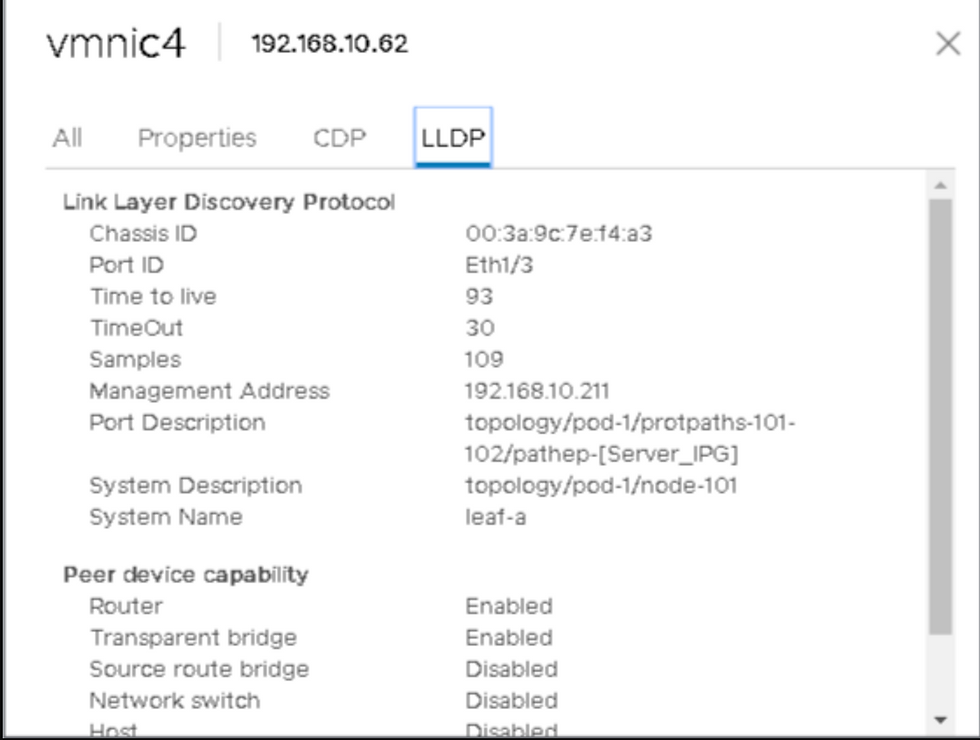
Step 9 : In the vSphere Client, remain on your VDS and go to Configure > Topology. Expand the first two uplinks, click ... and View Settings. Examine the neighbor information in the LLDP tab. Vmnic4 and vmnic5 should be connected to leaf-a and leaf-b Eth 1/3.

Vmnic4 should be connected to leaf-a Eth 1/3:
Vmnic5 should be connected to leaf-b Eth 1/3:

Step 10 : Go to VMs and Templates, select the APP_VM, Right Click and click the Edit Settings button in the top taskbar.

Step 11 : In the Virtual Hardware tab, in the Network Adapter 1 row, open the drop-down menu. Choose Browse and select the Sales|eCommerce_AP|App_EPG port group. Click OK twice.

Step 12 : Use the same method to assign the WEB_VM to the Web_EPG port group.
Disable Neighbor Discovery and Verify Connectivity
The interface policy group Server_IPG, defined for vPC connection to the ESXi, uses an LLDP policy with LLDP enabled. You will remove the host from the VDS, configure LLDP and CDP policies with LLDP and CDP disabled, and assign them to the interface policy group. When you re-add the host to the VDS (with LLDP and CDP disabled on ACI leafs), you will re-test the VM connectivity.
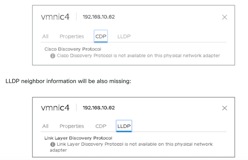
We will see that all Endpoint learned from Vmware host got disappeared.
Also, In the vSphere Client, within your VDS, go to Configure > Topology. Expand the first two uplinks, click ... and View Settings. Verify that the neighbor information is missing in the CDP and LLDP tabs.
Resolution Immediacy Explained
Immediate Resolution Immediacy
EPG policies (such as VLANs, contracts, and filters) are downloaded to the leaf when the hypervisor attaches to the VDS.
LLDP, CDP, or OpFlex must be running to detect the hypervisor-to-leaf connections.
If these protocols are disabled (e.g., LLDP is turned off), the hypervisor-to-leaf attachment cannot be resolved.
On Demand Resolution Immediacy
The APIC pushes the policy to the leaf when a hypervisor is attached to a VDS and a VM is placed in the port group (EPG).
This also requires LLDP or CDP to detect the hypervisor’s attachment, so it will not solve the current issue where LLDP is disabled.
Pre-Provision Resolution Immediacy (Default)
The policy is downloaded to the leaf before the hypervisor ever attaches to the VDS.
This “pre-provisions” the switch, so it doesn’t need LLDP or CDP to detect the hypervisor-to-leaf connection.
Enabling this default setting solves the problem caused by disabled LLDP.
In VMM domain if we change Resolution Immediacy to Pre-provision & see if that resolves the issue.
Expand the Web_EPG, select Domains (VMs and Bare-Metals), double-click the VMM domain association, change the Resolution Immediacy to Pre-provision and click OK.
It will resolve the issue and endpoint will be learn again.
Conclusion LLDP/CDP is just for visibility,
Troubleshooting ACI Vmware Issues
1. Verify VMM Domain Mapping
Navigate to the EPG experiencing the issue.
Confirm that a VMM domain is mapped to it.
2. Check Distributed Port Groups (DPGs) in vSphere
Open the vSphere Client.
Go to:Network → Datacenter (DC) → VDS switch (vCenter_VMM) → Networks → Distributed Port Groups
These port groups will reflect the EPG names, and you'll see the associated Access VLANs.
3. Check ESXi Hosts Connected to VDS
In vSphere:Network → DC → VDS → Hosts
This displays all ESXi hosts connected to the VDS.
4. Verify VMs Connected to DPGs
In vSphere:Network → DC → VDS → VMs
View all VMs connected to Distributed Port Groups.
5. Trace DPG to ESXi Host to Leaf Switch
In vSphere:Network → DC → VDS → Configure → Topology
Select a Distributed Port Group, and it will show:
Connected ESXi host(s)
Uplink interface (e.g., vmnic3)
View CDP/LLDP details to identify the Leaf switch interface the ESXi host is connected to.
6. Check VM's Port Group Association
Right-click the VM → Edit Settings
Go to:Virtual Hardware → Network Adapter
Confirm which Distributed Port Group the VM is using.
Best Practice
Always use Pre-Provision Resolution Immediacy (default setting) when configuring VMM domains for EPGs.
7. Version Compatibility
The DVS (Distributed Virtual Switch) version depends on the vCenter version.
If the ESXi version is incompatible, it may not be added to the DVS.
8. Check Loose Nodes (Unmanaged)
Go to:Fabric → Inventory → Fabric Membership → Unmanaged Fabric Nodes
9. Verify CDP/LLDP Configuration
If ESXi host is not appearing as a neighbour, check CDP/LLDP settings:
On APIC:
Virtual Networking → VMM Domains → VMware → Policy → vSwitch Policy → CDP/LLDP
On vCenter:
Network → VDS → Configure → Properties
On ESXi Host:
Host → Manage → Hardware → Physical NICs → Properties / Advanced Settings
Ensure LLDP is disabled .
10. For Cisco UCS B-Series (Blade Servers)
Ensure MAC Pinning is enabled from ACI:
Virtual Networking → VMware → vCenter Domain → Policy → vSwitch Policy → MAC Pinning
In vSphere:
Network → DC → VDS → Networks → Distributed Port Groups → Policies
Set load balancing to:"Route based on originating virtual port"
TSHOOT STEPS
Shard Leader Role: Only one APIC (shard leader) is responsible for sending configuration and collecting inventory for each VMM Domain.
Event Listening: Multiple APICs listen for vCenter events to ensure no events are missed if the shard leader fails.
APIC Structure: Each VMM Domain has one shard leader and two follower APICs.
Workload Distribution: Different VMM Domains may have the same or different shard leaders to balance the workload.
VMWare VMM Domain - vCenter connectivity Troubleshooting
Go to Virtual Networking —> Inventory —> VMM Domains —> name of VMMDomain(VDS)—> Controllers —> You will find ip address of venter in “Address field”
Login as root
APIC# show vmware domain name
Leader will show APIC with Shard Leader Role
a) Identifying the Shard Leader
APIC# show vmware domain name

b) Verifying Connectivity to vCenter (192.168.10.50)
apic1# ping 192.168.10.50

APIC# nslookup vcenter
c) Check if OOB or INB is used
apic1#bash
admin@apic1:~>route
d) Ensure Port 443 is allowed between all APICs and the vCenter, including any firewalls in the path of communication.
vCenter <-> APIC - HTTPS (TCP port 443) - communication
Let's check port 80
APIC # curl -v -k 192.168.10.50

Now check port 443
APIC# curl -v -k https://192.168.10.50

Verify that the shard leader has an established TCP connection on port 443 using the netstat command.
apic1:~>netstat -tulaen | grep 192.168.10.50

2 . VMware Inventory Troubleshooting
Purpose of Inventory Sync: Inventory sync events help the APIC stay updated on important changes in vCenter that require policy updates.
Types of Sync Events: There are two types of inventory syncs: full inventory sync and event-based inventory sync.
Full Inventory Sync: This happens every 24 hours by default but can also be triggered manually.
Event-Based Inventory Sync: This occurs during specific events, like when a virtual machine moves (vMotion) between hosts connected to different leaf switches.
APIC Actions During VM Movement: If a VM moves to a different host, the APIC will update the necessary settings on the leaf switches involved.
Importance of Syncing: If the APIC fails to sync properly with vCenter, it can cause issues, especially with on-demand deployment settings.
Error Reporting: If the sync fails or is incomplete, an error message will identify the problem.
Scenario 1 : If a virtual machine is moved to a different vCenter or has an invalid configuration (such as being connected to an old or deleted DVS), the vNIC will be reported as having operational issues.
Fault fltCompVNicOperationalIssues
Rule ID:2842
Explanation:
This fault is raised when ACI controller failed to update the properties of a VNIC (for instance, it can.
Code: F2842
Message: Operational issues detected for VNic name on VM name in VMM controller: hostOrIp with name name
Resolution:
Remediate the virtual machines indicated in the fault by assigning a valid port group on the affected vNIC
Scenario 2 — vCenter Administrator Modified a VMM Managed Object on vCenter:
It is not supported to modify objects managed by the APIC directly from vCenter. If an unsupported action is taken on vCenter, a fault will be triggered.
Fault fltCompCtrlrUnsupportedOperation
Rule ID:133
Explanation:
This fault is raised when deployment of given configuration fails for a Controller.
Code: F0133
Message: Unsupported remote operation on controller: hostOrIp with name name in datacenter rootContName
Resolution:If this scenario is encountered, try to undo the unsupported change in vCenter and then trigger an 'inventory sync
VMWare VMM Domain - vCenter controller - trigger inventory sync

VMware DVS Version
When creating a new vCenter controller as part of a VMM Domain, the default setting for the DVS Version will be to use the "vCenter Default". When selecting this, the DVS version will be created with the version of the vCenter.

VMWare VMM Domain - vCenter controller creation
This means that in the example of a vCenter running 6.5 and ESXi servers running 6.0, the APIC will create a DVS with version 6.5 and hence the vCenter administrator will be unable to add the ESXi servers running 6.0 into the ACI DVS.
Symptoms
APIC managed DVS - vCenter host addition - empty list

APIC managed DVS - vCenter host addition - incompatible hosts

Host Dynamic Discovery & it's Benefit
ACI automatically detects where hosts and virtual machines (VMs) are connected, unlike manual provisioning.
Efficient Policy Deployment: ACI deploys policies only on the nodes where they are needed, optimizing the use of hardware resources on leaf switches.
Resource Optimization: VLANs, SVIs, and zoning rules are applied only when an endpoint requires them, improving hardware efficiency.
Ease of Use for Admins: ACI automatically provisions VLANs and policies where VMs connect, reducing manual work for network administrators.
Information Gathering: The APIC uses data from various sources to determine where policies need to be applied.
VMWare VMM Domain — Deployment workflow
LLDP or CDP Exchange: LLDP or CDP is exchanged between the hypervisor and leaf switches.
Hosts Report Adjacency: Hosts send adjacency information to vCenter.
vCenter Notifies APIC: vCenter informs the APIC about the adjacency information.
APIC Awareness: The APIC learns about the host through inventory sync.
APIC Pushes Policy: The APIC applies the necessary policy to the leaf port.
Policy Removal: If adjacency information from vCenter is lost, the APIC can remove the policy.
This highlights the critical role of CDP/LLDP in the discovery process, making it essential to ensure they are correctly configured and both sides are using the same protocol.
Use Case for LooseNode / Intermediate Switch
In setups with a blade chassis, there might be an intermediate switch between the leaf switches and the hypervisor.
APIC's Role:
The APIC needs to connect (or "stitch") the communication path between the leaf switches and the hypervisor.
Protocol Requirements:
Different discovery protocols might be needed because the intermediate switch may require different protocols than the host.
Detection and Mapping:
ACI can identify the intermediate switch (known as a LooseNode or "Unmanaged Fabric Node") and map out the hypervisors connected through it.
Viewing LooseNodes:
You can see the detected LooseNodes in the ACI interface under: Fabric > Inventory > Fabric Membership > Unmanaged Fabric Nodes

With LLDP or CDP discovery enabled, ACI can figure out the topology (network layout) for these LooseNodes. This works because the hypervisor connected through the intermediate switch is managed via VMM integration, and the leaf switch has a direct connection to the intermediate switch.
Resolution Immediacy
Critical Services and VMM-Integrated DVS:
When critical services, like management connectivity to vCenter/ESXi, use a VMM-integrated DVS, it's important to use the Pre-provision Resolution Immediacy setting.
Static Configuration:
This setting disables dynamic host discovery, meaning policies and VLANs are always statically configured on the host-facing interfaces.
VLAN Deployment:
VMM VLANs are permanently applied to all interfaces linked to the AEP (Attached Entity Profile) referenced by the VMM Domain.
Preventing VLAN Removal:
This setup ensures that critical VLANs, such as those for management, are not accidentally removed due to issues with discovery protocols.
Here's a summary of the resolution immediacy settings:
On-Demand: Policy is applied when a connection is made between the leaf switch and host, and a VM is attached to the port group.
Immediate: Policy is applied as soon as a connection is made between the leaf switch and host.
Pre-provision: Policy is applied to all ports associated with an AEP that includes the VMM Domain, without needing any connection.
Troubleshooting Scenarios
VM Cannot Resolve ARP for its Default Gateway
Here , VMM integration is set up, and the DVS is added to the hypervisor, but the VM can't connect to its gateway in ACI. To fix the network connectivity for the VM, make sure the connection (adjacency) is established and VLANs are properly deployed.
Start by checking if the leaf switch has recognized the host. You can do this by running the show lldp neighbors or show cdp neighbors command on the leaf switch, depending on which protocol is being used.
Leaf101#show lldp neighbors
Now from host also you can check dvs list
Root login
Host # esxcli network vswitch dvs vmware list
# esxcfg
The above information can be seen through GUI as well
vCenter Web Client - host - vmnic LLDP/CDP adjacency details

Check cdp or lldp
If the leaf switch doesn’t detect the LLDP connection from the ESXi host, it might be because the network adapter is generating LLDP packets instead of the ESXi operating system.
Check if the network adapter has LLDP enabled and is taking over all LLDP information.
If so, disable LLDP on the adapter so that it’s managed by the vSwitch policy.
vSphere Client (under “Host” → “Manage” → “Hardware” → “Physical NICs” → “Properties” or “Advanced Settings” for a given NIC).
Another possible issue could be a mismatch between the discovery protocols used by the leaf switch and the ESXi hypervisor. Make sure both sides are using the same discovery protocol.
To verify that the CDP/LLDP settings are correctly aligned between ACI and the DVS, go to the APIC UI and navigate to: Virtual Networking > VMM Domains > VMware > Policy > vSwitch Policy. Ensure that either LLDP or CDP is enabled, but not both, as they cannot be used together.

In vCenter go to: Networking > VDS > Configure.
vCenter Web Client UI - VDS properties

Correct the LLDP/CDP settings if needed.
Then validate the APIC observes the ESXi host's LLDP/CDP neighborship against the leaf switch in the UI under Virtual Networking > VMM Domains > VMWare > Policy > Controller > Hypervisor > General.
APIC UI - VMWare VMM Domain - Hypervisor details

If this is showing expected values, then the user can validate that the VLAN is present on the port toward the host.
S1P1-Leaf101# show vlan encap-id 1035
vCenter/ESXi Management VMK Attached to APIC-Pushed DVS
vCenter and ESXi Management Traffic: When using VMM integrated DVS, take extra care to avoid issues with activating dynamic connections and VLANs.
vCenter Setup:
vCenter is usually set up before VMM integration.
Use a physical domain and static path to ensure the vCenter VM’s VLAN is always active on the leaf switches, even before VMM integration is complete.
Keep this static path in place even after VMM integration to ensure the EPG is always available.
ESXi Hypervisors:
According to the Cisco ACI Virtualization Guide, when migrating to the vDS, ensure the EPG for the VMK interface is deployed with the resolution immediacy set to Pre-provision.
This ensures the VLAN is always active on the leaf switches, without depending on LLDP/CDP discovery from the ESXi hosts.
Scenario Overview:
When vCenter or ESXi management traffic needs to use the VMM-integrated Distributed Virtual Switch (DVS), extra precautions are necessary to prevent issues with activating dynamic connections and required VLANs.
For vCenter:
Use a Physical Domain and Static Path:
Since vCenter is typically set up before VMM integration, configure a physical domain and a static path.
This ensures the vCenter VM encapsulation VLAN is always programmed on the leaf switches.
Allows the VLAN to be used even before VMM integration is fully established.
Maintain Static Path After VMM Integration:
Even after setting up VMM integration, keep the static path in place.
Ensures continuous availability of this Endpoint Group (EPG).
For ESXi Hypervisors:
Follow Cisco's Virtualization Guide:
When migrating to the vDS (virtual Distributed Switch), ensure the EPG for the VMkernel (VMK) interface is deployed with the resolution immediacy set to Pre-provision.
Benefits of Pre-provision Setting:
Guarantees the VLAN is always programmed on the leaf switches.
Eliminates the need to rely on LLDP/CDP discovery of the ESXi hosts.
Host Adjacencies not Discovered Behind LooseNode
Common Causes of LooseNode Discovery Issues:
CDP/LLDP is Not Enabled:
LLDP or CDP protocols must be enabled and actively exchanging information between the intermediate switch, the leaf switches, and the ESXi hosts.
In Cisco UCS environments, enable LLDP/CDP through a network control policy applied to the vNIC.
2. Change in Management IP Address:
If the management IP address of an LLDP/CDP neighbor changes, it can disrupt connectivity.
vCenter may detect the new management IP in the LLDP/CDP information but won't automatically update the APIC.
To fix this issue, manually trigger an inventory sync in the APIC.
3.VMM VLANs Not Added to the Intermediate Switch:
The APIC does not automatically configure VLANs on third-party blade or intermediate switches.
You need to manually add the VMM VLANs to the intermediate switch.
The Cisco UCS Manager (UCSM) integration app, called ExternalSwitch, is available from release 4.1(1) to assist with this.
Ensure that VLANs are configured and properly trunked:
Uplinks: Connect to the ACI leaf nodes.
Downlinks: Connect to the hosts.
F606391 - Missing Adjacencies for the Physical Adapter on the Host
It means there are missing CDP/LLDP adjacencies.
Hypervisor Uplink Load Balancing
Connecting Hypervisors with Multiple Uplinks:
When you connect hypervisors like ESXi to an ACI fabric, they usually have multiple uplinks.
It's recommended to connect each ESXi host to at least two leaf switches.
This setup helps reduce the impact of failures or during upgrades.
Optimizing Uplink Usage with Load Balancing:
VMware vCenter allows you to configure different load balancing algorithms.
These algorithms optimize how virtual machine (VM) traffic uses the hypervisor's uplinks.
Importance of Consistent Configuration:
It's crucial that all hypervisors and the ACI fabric are set up with the same load balancing algorithm.
If they aren't aligned, it can cause intermittent traffic drops.
Mismatched configurations can also lead to endpoints moving unexpectedly within the ACI fabric.
This can be seen in an ACI fabric by excessive alerts such as fault F3083
ACI has detected multiple MACs using the same IP address 172.16.202.237.
Rack Server
Different methods for connecting an ESXi host to an ACI fabric, these methods are grouped into two main categories: switch-independent and switch-dependent load balancing algorithms.
Switch-Independent Load Balancing Algorithms:
These allow connections without requiring any special configurations on the switches.
The hypervisor manages load balancing internally, so the switches do not need to be aware of or participate in the load balancing process.
Switch-Dependent Load Balancing Algorithms:
These require specific configurations to be applied to the switches involved.
The switches play an active role in the load balancing process, necessitating coordination between the hypervisor and the switch settings.
Teaming and ACI vSwitch Policy
VMware Teaming and Failover Mode | ACI vSwitch Policy | Description | ACI Access Policy Group - Port Channel Required |
Route based on the originating virtual port | MAC Pinning | Select an uplink based on the virtual port IDs on the switch. After the virtual switch selects an uplink for a virtual machine or a VMKernel adapter, it always forwards traffic through the same uplink for this virtual machine or VMKernel adapter. | No |
Route based on Source MAC hash | NA | Select an uplink based on a hash of the source MAC address | NA |
Explicit Failover Order | Use Explicit Failover Mode | From the list of active adapters, always use the highest order uplink that passes failover detection criteria. No actual load balancing is performed with this option. | No |
Link Aggregation(LAG) - IP Hash Based | Static Channel - Mode On | Select an uplink based on a hash of the source and destination IP addresses of each packet. For non-IP packets, the switch uses the data at those fields to compute the hash. IP-based teaming requires that on the ACI | Yes (channel mode set to 'on') |
VMware Teaming and Failover Mode | ACI vSwitch Policy | Description | ACI Access Policy Group - Port Channel Required |
side a port-channel / VPC is configured with 'mode on'. | |||
Link Aggregation(LAG) - LACP | LACP Active / Passive | Select an uplink based on a selected hash (20 different hash options available). LACP based teaming requires that on the ACI side a port-channel / VPC is configured with LACP enabled. Make sure to create an Enhanced Lag Policy in ACI and apply it to the VSwitch Policy. | Yes (channel mode set to 'LACP Active/Passive') |
Route based on Physical NIC Load (LBT) | MAC Pinning - Physical-NIC-load | Available for distributed port groups or distributed ports. Select an uplink based on the current load of the physical network adapters connected to the port group or port. If an uplink remains busy at 75 percent or higher for 30 seconds, the host vSwitch moves a part of the virtual machine traffic to a physical adapter that has free capacity. |
Teaming and ACI vSwitch Policy
VMware Teaming and Failover Modes:
Route Based on the Originating Virtual Port (MAC Pinning):
Description:
Selects an uplink based on the virtual port IDs on the switch.
Once an uplink is chosen for a VM or VMKernel adapter, all traffic for that VM or adapter always uses the same uplink.
ACI Requirement: Not required.
Route Based on Source MAC Hash:
Description:
Selects an uplink based on a hash of the source MAC address.
ACI Requirement: Not applicable.
Explicit Failover Order:
Description:
Uses the highest priority uplink that is active and passes failover checks.
No load balancing is performed.
ACI Requirement: Not required.
Link Aggregation (LAG) - IP Hash Based:
Description:
Selects an uplink based on a hash of the source and destination IP addresses of each packet.
For non-IP packets, uses available data fields to compute the hash.
ACI Requirement:
Yes, the channel mode must be set to 'on' in ACI.
Link Aggregation (LAG) - LACP:
Description:
Selects an uplink based on a chosen hash method (20 different options available).
Requires LACP (Link Aggregation Control Protocol) to be enabled on the ACI side.
An Enhanced Lag Policy must be created in ACI and applied to the vSwitch Policy.
ACI Requirement:
Yes, the channel mode must be set to 'LACP Active/Passive'.
Route Based on Physical NIC Load (LBT - Load-Based Teaming):
Description:
Available for distributed port groups or distributed ports.
Selects an uplink based on the current load of the physical network adapters connected to the port group or port.
If an uplink is busy at 75% or higher for 30 seconds, the host vSwitch moves some of the VM traffic to a less busy adapter.
ACI Requirement: Not specifically required, but helps in balancing traffic loads.
ACI vSwitch Policy Descriptions:
ACI Access Policy Group - Port Channel Required:
Description:
For setups where a port-channel or Virtual Port Channel (VPC) is configured with 'mode on'.
Ensures that VLANs are consistently applied across all ports in the channel.
Link Aggregation (LAG) - IP Hash Based:
Description:
Uses IP hash for selecting uplinks.
Requires static channel mode set to 'on' in ACI.
Link Aggregation (LAG) - LACP:
Description:
Uses LACP for dynamic link aggregation.
Requires creating an Enhanced Lag Policy in ACI and applying it to the vSwitch Policy.
Ensures uplinks are managed with LACP Active/Passive settings.

Key Points to Ensure Proper Configuration:
Consistency:
All hypervisors and the ACI fabric must use the same load balancing algorithm to ensure proper connectivity and traffic flow.
Avoiding Traffic Issues:
Mismatched configurations can lead to intermittent traffic drops and unexpected endpoint movements within the ACI fabric.
Optimizing Uplinks:
Proper load balancing ensures efficient use of uplinks and minimizes the impact of failures or maintenance activities.
By following these guidelines and ensuring that both VMware and ACI configurations are aligned, you can achieve reliable and efficient network connectivity for your hypervisors within the ACI fabric.
Cisco UCS B-Series Use Case
Connection Setup:
Cisco UCS B-Series servers connect to UCS Fabric Interconnects (FIs) within their chassis.
These FIs do not share a unified dataplane, which can cause differences in load-balancing methods between ACI leaf switches and vSwitches.
Key Points to Remember:
Port-Channels:
Each UCS Fabric Interconnect (FI) connects to ACI leaf switches using a port-channel.
FI Interconnections:
UCS FIs are directly connected to each other only for heartbeat (monitoring) purposes, not for handling data traffic.
vNIC Assignment:
Each blade server's virtual NIC (vNIC) is either:
Pinned to a specific UCS FI, or
Uses a path to an FI through UCS Fabric Failover (Active-Standby) mode.
Load Balancing Issues:
Using IP-hash algorithms on the ESXi host vSwitch can cause MAC address flapping on the UCS FIs, leading to network instability.

MAC Pinning Configuration:
Setup in ACI:
When MAC Pinning is configured in the Port-Channel Policy as part of the vSwitch Policy in ACI, it is reflected as "Route based on the originating virtual port" in the teaming settings of the port groups on the Virtual Distributed Switch (VDS).
How to View Configuration:
To verify this setup, navigate through the following path in VMware vCenter

VMWare vCenter — ACI VDS — Port Group — Load Balancing setting
This structured approach ensures that Cisco UCS B-Series servers are properly integrated with the ACI fabric, optimizing network performance and stability.


-------------------------------------------------------------------------------------------------------------------------------
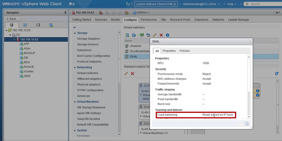
VM "WEB" is connected to interface of "DUAL_VLAN11"of vSwitch "DUAL"
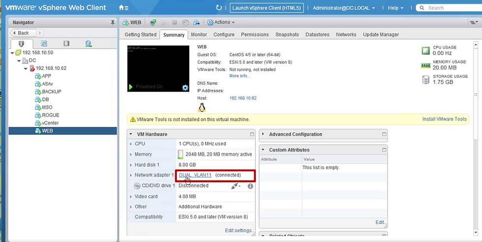
In Esxi host there are total 3 vSwitch one out of them is "DUAL"
Here all three interfaces of "DUAL" switch are connected to interface vmnic4 & vmnic5.
On clicking "blue icon" vmnic4 and vmnic5 & further clicking on CDP or LLDP it will show which leaf switch & interface it's connected.

Switch "DUAL" load balancing method id "Route based on IP hash"
Troubleshooting Role-Based Access Control (RBAC) with vCenter
When RBAC Issues Occur
Often happen during the initial setup of a VMM Domain.
Can also occur if a vCenter administrator changes the permissions of the user account linked to the VMM Domain after setup.
Possible Symptoms
Partial or complete failure to deploy new services (e.g., Distributed Virtual Switch creation, port group creation).
Some objects deploy successfully while others fail.
Missing or incomplete operational inventory in ACI administrator views.
Faults for unsupported vCenter operations (e.g., port group deployment failure) or related issues.
vCenter controller may appear offline with faults indicating connectivity or credential problems.
How to Verify and Resolve
Log in to vCenter using the exact same credentials defined in the VMM Domain configuration.
Try performing the same actions (e.g., creating a port group).
If these operations fail when logged in directly to vCenter, it means the user does not have the required permissions.
Update the user’s permissions in vCenter to fix the issue.
-----------------------------------------------------------------------------------------
Troubleshooting steps focused on resolving Cisco ACI VMM (Virtual Machine Manager) domain issues, specifically related to VMware vCenter integration.
I. Initial Checks & Basic Connectivity
Verify APIC-vCenter Connectivity:
Check VMM Domain Status in APIC: Navigate to Virtual Networking > VMware > Domains > Your-vCenter-Domain. Check the overall status and health score.
Check Controller Status: Under the VMM Domain, go to the Controller section. Verify the IP address or FQDN of the vCenter is correct and reachable from the APIC's OOB or In-Band management network (depending on your configuration).
Verify Credentials: Ensure the credentials used in the VMM Domain's credential policy (Virtual Networking > VMware > Credentials) are correct and have sufficient privileges within vCenter. Test these credentials by logging into vCenter directly.
Check Connectivity: Ensure basic network connectivity (ping, appropriate ports open on firewalls if any) exists between the APIC controllers and the vCenter server, using the management network configured for the VMM domain.
Check Faults in APIC:
VMM Domain Faults: Navigate to Virtual Networking > VMware > Domains > Your-vCenter-Domain > Faults. Review any active faults. Fault codes often provide specific reasons for failure (e.g., connection errors, credential failures, configuration mismatches).
System Faults: Check System > Faults and filter for faults related to VMM or your specific VMM domain name.
II. Configuration Verification (APIC & vCenter)
Verify VMM Domain Configuration:
Datacenter Name: Ensure the Datacenter name configured in the APIC VMM Domain exactly matches the Datacenter name in vCenter (case-sensitive).
VLAN Pool: Confirm a VLAN Pool with Dynamic Allocation is associated with the VMM Domain. Ensure this pool has available VLANs within the specified range(s). Static allocation can be used but requires careful manual management when associating EPGs.
Attachable Access Entity Profile (AEP): Verify the correct AEP is associated with the VMM Domain. This AEP links the VMM domain to the physical infrastructure (Interface Policy Groups and interfaces) where the ESXi hosts connect. Without the correct AEP association, policies won't be pushed to the relevant leaf ports.
Interface Policy Group (IPG) & AEP: Ensure the IPGs used for the ESXi host uplinks are associated with the same AEP used by the VMM Domain.
CDP/LLDP Policy: Ensure the CDP or LLDP policy configured in the VMM Domain settings matches the policy enabled on the associated Interface Policy Group (IPG) and the vSphere Distributed Switch (vDS) settings in vCenter. Both sides should be configured consistently (e.g., both using CDP, or both using LLDP).
Verify EPG Association:
EPG to VMM Domain: Navigate to the Application EPG (Tenants > Your-Tenant > Application Profiles > Your-App-Profile > Application EPGs > Your-EPG > Domains (VMs and Bare-Metal)). Ensure the correct VMM domain is associated.
Resolution Immediacy: Check the Resolution Immediacy setting for the EPG-to-Domain association. Immediate or On-Demand determines when policies are pushed. Pre-provision is often used for VMkernel port EPGs.
Deployment Immediacy: Verify the Deployment Immediacy setting.
Verify vCenter Objects Created by ACI:
Distributed Virtual Switch (DVS): Log in to vCenter. Navigate to Networking. Verify that a DVS matching the ACI VMM Domain name has been created (or that ACI is managing the pre-existing DVS if configured that way). Check its health status in vCenter. Note: If the DVS was accidentally deleted in vCenter, ACI may not push it again automatically. You might need to disconnect/reconnect the VMM controller in APIC.
Port Groups: Check if port groups corresponding to your ACI EPGs have been created on the DVS. The naming convention is typically Tenant|AppProfile|EPG. If port groups are missing, check APIC faults and EPG-to-domain association.
Host Addition to DVS: Verify that the ESXi hosts are successfully added to the ACI-managed DVS in vCenter. Check the Hosts tab under the DVS configuration. Ensure the correct physical NICs (vmnics) from the ESXi hosts are assigned as uplinks.
III. ESXi Host & Leaf Switch Verification
Check Leaf Switch Programming:
LLDP/CDP Neighbors: SSH into the leaf switches connected to the ESXi hosts. Use show lldp neighbors or show cdp neighbors to verify that the leaf switch sees the ESXi host's NICs.
VLANs and EPGs: On the leaf switch CLI, use show vlan extended | grep <vmm-domain-name> or show vlan extended | grep <epg-name> to verify that the VLANs associated with the VMM domain EPGs are programmed on the correct interfaces connected to the hosts. Check if the Encap VLAN (wire VLAN) matches what's expected.
Endpoints: Use show endpoint interface <interface_id> or show endpoint vlan <vlan_id> to see if the leaf switch is learning the MAC/IP addresses of the VMs attached to the VMM EPGs
Check ESXi Host Configuration:
vmnic Assignment: Ensure the correct physical NICs (vmnics) on the ESXi hosts are assigned to the ACI-managed DVS uplinks.
VM Network Assignment: Verify that the virtual machines are connected to the correct Port Groups (corresponding to ACI EPGs) on the DVS.
VMkernel Adapters: If using VMM integration for VMkernel ports (e.g., vMotion, iSCSI, Management), ensure the VMkernel adapters are assigned to the correct ACI-created port groups and that their EPGs have the appropriate contracts and Resolution Immediacy (often Pre-provision).
IV. Advanced Troubleshooting
Check Version Compatibility: Crucially, verify that your versions of Cisco APIC/ACI, VMware vCenter, and ESXi are compatible. Check the official Cisco ACI Virtualization Compatibility Matrix. Mismatched versions are a common cause of integration failures or unexpected behavior.
Use APIC CLI Tools:
•moquery: Use moquery -c faultInst to query faults. You can filter using -f 'fault.Inst.dn*="<dn_of_vmm_domain>"' to narrow down faults related to your VMM domain.
Query classes like vmmDomP, vmmCtrlrP, infraAccPortGrp, infraRsVlanNs (for VLAN pool association) can provide detailed configuration status.status.
Review Logs:
APIC Logs: Check relevant process logs on the APIC (e.g., vmmmgr).
vCenter Event Logs: Monitor vCenter events for tasks initiated by the ACI user account. Look for successes or failures related to DVS and port group creation/modification.
Isolate the Issue:
Test Basic EPG (Non-VMM): Can you configure a standard EPG (using a Physical Domain and static path/VLAN binding) on the same leaf ports and achieve connectivity? This helps isolate whether the issue is specific to VMM integration or a more fundamental fabric problem.
Simplify: If multiple issues exist, try simplifying the configuration. Test with a single ESXi host, a single EPG, etc.
Comments