
Endpoint Definition:
An Endpoint comprises:
One MAC Address
Zero or More IP Addresses
Traditional Network Address Tables: In conventional networking, three primary tables are utilized to manage the network addresses of external devices:
MAC Address Table
Purpose: Facilitates Layer 2 Forwarding
Routing Information Base (RIB)
Purpose: Enables Layer 3 Forwarding
Address Resolution Protocol (ARP) Table
Purpose: Associates IP Addresses with MAC Addresses
Cisco ACI replaced the MAC address table and ARP table with a single table called the endpoint table.
Packet Transmission Scenarios:
When a leaf switch needs to send packets between Host A and Host B, the approach varies based on their connections and network configurations.
A) Source Leaf Knows the Destination – Destination is on the Same Leaf
Condition:
The destination MAC address is known to the ingress leaf.
The destination resides on the same leaf.
Action:
Forward the packet to the local port.
Operates similarly to traditional Layer 2 or Layer 3 forwarding.
B) Source Leaf Knows the Destination – Destination is on a Different Leaf
Condition:
The destination MAC address is known to the ingress leaf.
The destination resides on a different leaf.
Action:
Forward the packet directly to the destination leaf.
C) Source Leaf Does Not Know the Destination – Spine-Proxy Mode
Condition:
The source leaf does not know the destination MAC address.
Actions:
Unicast Layer 3 Routed Packet
The packet is a unicast Layer 3 routed packet.
The destination IP is unknown to the ingress leaf but belongs to one of the Bridge Domain (BD) subnets on the ingress leaf.
Action: Use Spine-Proxy mode to forward the packet.
Unicast Layer 2 Switched Packet
The packet is a unicast Layer 2 switched packet.
The BD Layer 2 Unknown Unicast mode is set to hardware-proxy.
Action: Use Spine-Proxy mode to forward the packet.
Broadcast ARP Request
The packet is a broadcast ARP request.
BD ARP Flooding is disabled.
The ARP target IP is unknown to the ingress leaf and belongs to one of the BD subnets on the ingress leaf.
Action: Use Spine-Proxy mode to forward the ARP request.
D) Source Leaf Does Not Know the Destination – Flood Mode
Condition:
The source leaf does not know the destination MAC address.
Actions:
Unicast Layer 2 Switched Packet
The packet is a unicast Layer 2 switched packet.
The BD Layer 2 Unknown Unicast mode is set to flood.
Action: Flood the packet across the network.
Broadcast ARP Request
The packet is a broadcast ARP request.
BD ARP Flooding is enabled.
Action: Flood the ARP request throughout the network.
Types of VLANs
1. Access Encap VLAN ID
Purpose:
Facilitates communication with external devices.
Characteristics:
Represents a VLAN ID on both the ACI and the external device (i.e., a VLAN on the wire).
Mapping:
Internally mapped to a Platform-Independent (PI) VLAN ID.
2. Platform-Independent (PI) VLAN ID
Purpose:
Utilized internally within a specific leaf; not shared with other leaves.
Characteristics:
Can map the internal ID to:
Access Encap VLAN ID
VXLAN ID
Bridge Domain Switch Virtual Interface (SVI) ID
Usage:
Enables retrieval of information about the Endpoint Group (EPG).
Note:
While the same Access Encap VLAN IDs can exist on different leaves, PI VLAN IDs may vary.
3. VXLAN ID
Purpose:
Ensures efficient forwarding across the entire fabric by providing a shared identifier among all nodes.
Characteristics:
Identified as VXLAN Network Identifier (VNID).
Usage:
Bridge Domain VNID: Used for bridging traffic within the same bridge domain.
VRF VNID: Employed for routing traffic across different Virtual Routing and Forwarding (VRF) instances.

If you want to see endpoints learned in specific EPG then simply go to the path
Tenant -> Application Profile → EGP

Check number of endpoints present in particular VRF in leaf
Leaf 1 # Show vrf
# show endpoint vrf Tenant:VRF

Types of Endpoints
Physical local endpoint (PL)
This endpoint is learned and physically attached to the local leaf.


2) Virtual local endpoint (VL)
This endpoint is still local to the leaf, but it is behind a virtual switch (Cisco Application Virtual Switch [AVS] or Cisco ACI Virtual Edge [AVE]).
Leaf# show endpoint ip 192.168.66.2

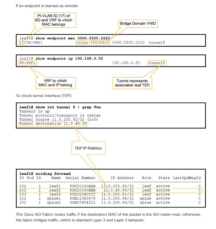
3) Remote endpoint (XR)
It represents an endpoint on another leaf. Remote endpoint does not have the L flag.
Leaf# show endpoint mac 0000.5555.2222
Leaf# show endpoint IP 192.168.0.53

4) On-peer endpoint (O)
This endpoint is on another leaf but that leaf is a vPC peer of your local leaf switch and the endpoint is connected to an orphan port on that vPC peer. This endpoint type has a specific O flag that is shown in the show endpoint command output.

COOP DATABASE
To get VRF & BD Vnid
Leaf # show system internal epm endpoint ip 10.0.1.1

Spine# show coop internal info repo ep key “Bridge Domain VNID” “EP Mac” | egrep ‘vnid|mac|id|Real’

Spine# show coop internal info repo ep key 15826915 0000.5555.1111 | egrep ‘vnid|mac|id|Real’

Endpoint Database on GUI ---> Inventory --> Spine switch --> Protocols --> COOP --> Endpoint Database.
NIC Teaming to ACI Fabric
1. Active/Standby NIC Teaming
Configuration:
One interface is active.
One or more interfaces are in a standby state.
Failover Implementations:
A) MAC Address Remains Identical After Failover
Behavior:
The MAC address of the active interface does not change during failover.
Advantages:
Bridge Domain Configuration: No changes required if the new active interface starts sending traffic immediately after failover, as the endpoint information (MAC, IP, and their combination) remains unchanged.
COOP Database Update: The endpoint-to-TEP (Tunnel Endpoint) mapping in the COOP database on spine switches is updated automatically, similar to a normal endpoint move.
B) MAC Address Changes After Failover
Behavior:
The newly active interface uses its own MAC address to send traffic after failover.
Requirements:
IP-to-MAC Mapping Update: Must be updated on all servers within the same Layer 2 domain.
Server Actions: Servers send a GARP/RARP request after failover.
Bridge Domain Configuration: Must enable ARP flooding to ensure the GARP request reaches all servers in the bridge domain.
IP Data Plane Learning: Must be set to off (default is enabled).
2. Active/Active NIC Teaming
Configuration:
Servers use active/active NIC teaming (e.g., Transmit Load Balancing), sending the same source IP from multiple NICs with different MAC addresses.
Challenges:
IP Flapping: Causes IP flapping between MAC addresses in ACI endpoint learning due to IP data plane learning.
Recommended Connectivity Options:
A) Switch to Active/Standby NIC Teaming
Adjust the teaming configuration to active/standby to prevent IP flapping.
B) Use Port Channel for Active/Active Scenarios
Implement a Port Channel to handle active/active NIC teaming without causing IP flapping.
Alternative Solution:
Disable IP Data Plane Learning:
Configuration: Disable IP data plane learning in the VRF (Virtual Routing and Forwarding) configuration.
Effect: The Endpoint table is updated through ARP (MAC-IP mapping) instead of relying on IP data plane learning.
Endpoint learning optimisation options.
Limit IP Learning to Subnet in Bridge Domain
Enable Limit IP Learning to Subnet Option
Functionality:
Restricts local endpoint IP learning to only include IP addresses within the subnets configured on the bridge domain.
Default Setting:
Enabled by default, ensuring controlled IP learning for local endpoints.
Impact on Local Endpoint IP Learning
Configured Subnet Example:
If a bridge domain is set with a subnet address of 192.168.1.254/24:
Allowed IPs: Only IP addresses within the 192.168.1.0/24 range are learned locally.
Blocked IPs: IP addresses outside this range, such as 192.168.2.1/24, are not learned locally.
Benefit:
Prevents unnecessary IP learning, enhancing network efficiency and security.
Effect on Remote Endpoint IP Learning
No Limitation:
The Limit IP Learning to Subnet option does not affect remote endpoint IP learning.
Remote leaves continue to learn both IP and MAC addresses without restrictions.
Additional Notes
MAC Address Learning:
Local Leaf:
Continues to learn the MAC address of hosts, even if their IP subnet isn't configured in the bridge domain.
Remote Leaf:
Learns both the IP and MAC addresses of the endpoints.
Packet Handling:
Although the local leaf does not learn the IP address for unconfigured subnets, it does not drop the packet.
This ensures seamless packet forwarding while maintaining optimized IP learning.

2) Through Global enforce subnet check
Purpose:
Endpoint Validation: Ensures Cisco ACI only learns endpoints with IP addresses that belong to the configured bridge domain subnets.
Key Functionalities:
Local Endpoint Learning:
Condition: Only IP addresses within the bridge domain's configured subnets are learned.
Remote Endpoint Learning:
Condition: Leaf switches learn remote entries only if their IP addresses belong to the VRF's associated bridge domain subnets.
Prevention: Blocks learning of IP addresses not configured as subnets on the bridge domains of the VRF.
Configuration Steps:
Enable Feature:
Navigate to System Settings > Fabric Wide Settings.
Activate: Enable the Enforce Subnet Check option.
Impact on Learning Processes:
MAC and IP Address Learning:
Restriction: Limits the learning of both MAC addresses and IP addresses when IP learning is triggered.
Security Enhancement:
IP Spoofing Prevention:
Scenario: Blocks endpoints from sending packets with source IP addresses that do not belong to any of the bridge domains on the VRF instance.
Example: Prevents use of IP addresses that exist behind the Layer 3 Outside connection from being learned improperly.
Operational Behavior:
Packet Handling:
Allowed Packets: Packets with source IPs within the configured bridge domain subnets are learned normally.
Blocked Packets: Packets with source IPs outside the configured subnets are not learned, enhancing network security.
COOP Database Integrity:
Note: Entries in the COOP (Consistent Overlay Operation Protocol) database are not cleared when the Enforce Subnet Check feature is enabled.
Additional Considerations:
Default State:
Disabled/Enabled: Verify the default state of the feature in your Cisco ACI deployment to ensure it aligns with your network security policies.
Network Design:
Ensure that all necessary subnets are correctly configured within the bridge domains to avoid unintended blocking of legitimate traffic.

3) IP Data-Plane Learning on Specific VRF
Location in Cisco ACI Interface:
Path: Tenant > Networking > VRFs
Default Setting:
Enabled by default
Behaviour When IP Data-Plane Learning is Disabled:
Endpoint Learning Adjustments:
Local MACs and Remote MACs:
Continues to Learn: Both local and remote MAC addresses are still learned via the data plane.
Local IP Addresses:
Not Learned via Data Plane: Local IPs are no longer learned through the data plane.
Learned via Control Plane: Local IPs are instead learned through ARP/GARP/Neighbor Discovery (ND) processes via the control plane.
Remote IP Addresses:
Unicast Packets: Remote IPs are not learned from unicast packets via the data plane.
Multicast Packets: Remote IPs are learned from multicast packets via the data plane.
Handling Existing Endpoint Entries:
Remote IP Endpoints:
Flushed Immediately: All existing remote IP endpoints are removed from the learning table upon disabling.
Local IP Endpoints:
Not Immediately Flushed: Local IP endpoints remain in the table.
Aging Out: These entries will eventually expire unless maintained by control plane packets such as ARP.
When to Disable IP Data-Plane Learning Option:
Handling Same-Source IP from Multiple Locations:
Issue: Receiving traffic with the same source IP from different locations can cause inconsistent endpoint IP and MAC bindings due to data plane traffic.
Use Cases:
Mainframe Virtual IP Address (VIPA) Connectivity: Ensures stable endpoint learning for mainframe systems.
Dynamic Load-Balancing NIC Teaming on Microsoft Windows: Prevents IP and MAC binding conflicts in load-balanced environments.
Multiple Devices Sharing the Same IP (Virtual IP):
Scenario: When devices share a virtual IP (VIP), such as during an F5 failover, the ACI fabric may learn the VIP from multiple sources via the data plane.
Solution: Disabling IP Data-Plane Learning prevents the fabric from learning conflicting VIP entries from different locations.
Security and Network Integrity:
Prevents IP Spoofing:
Function: Blocks endpoints from sending packets with source IP addresses that do not belong to any of the bridge domains on the VRF instance.
Example: Stops the use of IP addresses that exist behind a Layer 3 Outside connection from being learned improperly.
COOP Database Integrity:
Note: Entries in the COOP (Consistent Overlay Operation Protocol) database are not cleared when the Enforce Subnet Check feature is enabled.
Additional Considerations:
Control Plane Dependencies:
ARP/GARP/ND: Ensure that control plane mechanisms are properly configured to maintain accurate IP and MAC mappings for local endpoints.
Network Design Implications:
Bridge Domain Configuration: Verify that all necessary subnets are correctly configured within the bridge domains to avoid unintended blocking of legitimate traffic.
Failover Mechanisms: Ensure that failover processes are compatible with the disabled IP Data-Plane Learning to maintain network stability.

Endpoint Loop Protection
Feature Overview:
Definition: Endpoint Loop Protection is a global feature designed to prevent MAC address flapping within the Cisco ACI fabric.
Scope:
Global Configuration: Configured at the global level.
Applicability: Effective across all bridge domains within the fabric.
Default State:
Disabled: The feature is disabled by default.
Configuration Steps:
Navigation Path:
Go to System > System Settings > Endpoint Controls > Ep Loop Protection (located near Rogue EP Control).
Enabling the Feature:
Select Enable to activate Endpoint Loop Protection.
Operational Mechanism:
Detection Criteria:
MAC Address Flapping: The feature monitors for instances where an endpoint's MAC address flaps (moves) between two interfaces.
Threshold: Triggered when the same MAC address flaps more than a specified number of times within a defined time interval.
Configurable Parameters:
Loop Detection Interval:
Description: The time window during which MAC address movements are monitored.
Default Value: 60 seconds
Customization: Can be adjusted based on network requirements to define the sensitivity of loop detection.
Loop Detection Multiplication Factor:
Description: The number of allowable MAC address movements (flaps) within the detection interval before action is taken.
Default Value: 4
Customization: Adjust this factor to control how tolerant the system is to MAC address movements before initiating protective actions.
Action on Detection:
Port Disable Option:
Behavior: Disables one of the ports to which the flapping endpoint is connected.
Use Case: Ideal for scenarios where a specific port is identified as the source of the loop.
BD Learn Disable Option:
Behavior: Disables MAC learning within the affected bridge domain.
Use Case: Suitable for broader loop scenarios affecting multiple endpoints within the bridge domain.
Behavioral Outcomes:
Excessive Endpoint Movement:
Single Endpoint:
Cause: Likely due to an incorrect NIC-teaming configuration rather than an actual network loop.
Action: Port Disable or BD Learn Disable can help isolate and rectify the misconfiguration.
Multiple Endpoints:
Cause: Indicative of a genuine network loop affecting multiple devices.
Action: Disabling learning within the bridge domain is more effective in mitigating widespread loop issues.
Benefits:
Prevents Network Instability: By detecting and mitigating MAC address flapping, the feature helps maintain network stability and performance.
Enhances Security: Reduces the risk of network issues caused by misconfigurations or malicious activities leading to MAC address flapping.
Automated Protection: Provides automated responses to loop conditions, minimizing the need for manual intervention.
Additional Notes:
Non-Impact on COOP Database: Enabling or configuring Endpoint Loop Protection does not clear entries in the COOP (Consistent Overlay Operation Protocol) database.
Monitoring and Alerts: It is advisable to monitor Endpoint Loop Protection alerts to promptly address any underlying network issues that trigger protective actions.
Rogue Endpoint Control
Rogue Endpoint Control is a vital feature within Cisco ACI that enhances network stability by managing endpoints exhibiting erratic behavior. This feature specifically targets MAC or IP addresses that frequently move between ports, mitigating potential disruptions and maintaining the integrity of the network fabric.
Feature Overview
Purpose:
Identify and Manage Misbehaving Endpoints: Detects endpoints (identified by MAC or IP addresses) that exhibit excessive movement between ports.
Scope:
Global Application: Applies universally across all bridge domains within the Cisco ACI fabric.
Default State:
Disabled: The Rogue Endpoint Control feature is disabled by default to prevent unintended quarantining of legitimate endpoints.
Configuration Steps
Navigate to the Feature:
Path: System > System Settings > Endpoint Controls > Rogue Endpoint Control (located near Rogue EP Control).
Enable the Feature:
Action: Select Enable to activate Rogue Endpoint Control.
Configurable Parameters
1. Rogue Endpoint Detection Interval
Description: Defines the time window for detecting rogue endpoints.
Default Value: 60 seconds
Customization: Adjust based on network traffic patterns to fine-tune sensitivity.
2. Rogue Endpoint Detection Multiplication Factor
Description: Specifies the number of allowable endpoint movements within the detection interval before declaring it rogue.
Default Value: 4
Customization: Modify to control the threshold for endpoint movement tolerance.
3. Hold Interval
Description: Determines the duration for which the endpoint remains quarantined after being declared rogue.
Default Value: 1800 seconds (30 minutes)
Behavior During Hold Interval:
Learning Disabled: Prevents Cisco ACI from learning new information about the endpoint.
Traffic Dropped: Stops all traffic to and from the rogue endpoint.
Post Hold Interval: The endpoint is automatically deleted from the system.
Operational Mechanism
Detection Process:
MAC Address Flapping: Monitors for MAC addresses that move between two or more interfaces more than the specified multiplication factor within the detection interval.
Quarantining Behavior:
Isolation: Only the misbehaving endpoint is quarantined, ensuring minimal impact on the overall network.
TEP and Port Stability: Maintains the Tunnel Endpoint (TEP) and port association for a set duration, preventing further learning and traffic from the problematic endpoint.
Fault Notification:
Alert Generation: Raises a fault to facilitate easy identification and troubleshooting of the problematic endpoint.
Behavioral Outcomes
Single Endpoint Movement:
Cause: Often results from incorrect NIC teaming configurations rather than actual network loops.
Action: Quarantines the single endpoint without affecting other network components.
Multiple Endpoints Movement:
Cause: Indicative of genuine Layer 2 loops affecting multiple devices.
Action: Quarantines each problematic endpoint individually, mitigating the impact on the COOP (Consistent Overlay Operation Protocol) control plane.
Benefits
Enhanced Network Stability:
Prevents Disruptions: By isolating misbehaving endpoints, it maintains the overall health and performance of the network.
Improved Security:
Mitigates IP Spoofing: Reduces the risk of malicious activities that could exploit endpoint movements.
Simplified Troubleshooting:
Fault Alerts: Facilitates quick identification and resolution of network issues related to rogue endpoints.
Minimized Impact on Legitimate Traffic:
Selective Quarantining: Ensures that only problematic endpoints are affected, preserving normal network operations.
Additional Notes
Layer 2 Loops:
Mitigation, Not Prevention: Rogue Endpoint Control does not stop Layer 2 loops but mitigates their impact by quarantining affected endpoints.
Clearing Rogue Endpoints:
Procedure:
Navigate to Inventory > POD > Switch.
Action: Right-click on the switch and select Clear Rogue Endpoint.
Verification: Check if the Rogue Endpoint entry has been removed.
Handling Incorrect Configurations:
NIC Teaming Issues: Addresses scenarios where incorrect NIC teaming configurations cause endpoint flapping by stopping learning for the offending endpoint and raising relevant faults.
Recommendation:
Enable Rogue Endpoint Control: It is recommended to enable this feature to proactively manage and mitigate endpoint-related issues, despite it being disabled by default.

Clearing an Endpoint in Cisco ACI
The following steps outline the process to clear an endpoint within the Cisco ACI fabric, including verification and chip-level clearance.
1. Clear the Endpoint from the Leaf Switch
Objective: Remove the specific endpoint from the designated leaf switch.
APIC1# clear endpoints leaf 101 tenant T1 vrf V1
2. Verify Endpoint Deletion
Objective: Confirm that the endpoint has been successfully removed from the leaf switch.
APIC# fabric 101 show endpoint
3. Clear the Endpoint at the Chip Level
Objective: Ensure the endpoint is completely removed from the leaf switch's internal processing.
leaf1# vsh -c "clear system internal epm endpoint key vrf T1:V1 ip 1.1.1.1"
leaf1#clear system internal epm endpoint all <-- To clear all endpoints learned on switch of all vrf
4. Propagate Clearance via COOP on Spine Switches
Objective: Ensure that the endpoint is also cleared from the spine switches using the Consistent Overlay Operation Protocol (COOP).
a. Verify COOP Database on Spine Switch (Node 201):
APIC# fabric 201 show coop internal info ip-db | grep -A10 10.1.1.1
Explanation:
fabric 201: Refers to the spine switch with ID 201.
ip-db: Accesses the IP database within COOP.
grep -A10 10.1.1.1: Filters the output to display entries related to the IP 1.1.1.1 with 10 lines of context after the match.
b. Display All Endpoints in the Fabric:
Spine# show coop internal info repo ap
Explanation:
repo ap: Accesses the repository of all endpoints within the fabric.
This command helps verify that the endpoint has been removed from all spine switches.
5. Additional Verification and Cleanup
Objective: Ensure complete removal and consistency across the fabric.
Steps:
Check Rogue Endpoint Entries:
Navigate to Inventory > POD > Switch.
Action: Right-click on the switch and select Clear Rogue Endpoint if necessary.
Verification: Confirm that the Rogue Endpoint entry has been removed.
Note:
Endpoint Deletion Propagation: After clearing endpoints from the leaf switches, the removal propagates automatically via COOP to the spine switches, ensuring consistency across the entire fabric.
Endpoint Aging: Existing local IP endpoints are not immediately flushed but will age out unless maintained by control plane packets such as ARP.
Bounce Entries in Cisco ACI
Bounce entries help manage and update endpoint information when devices move between Cisco ACI leaf switches.
Scenarios Triggering Endpoint Movement:
Failover Events: When a primary device fails and a backup takes over.
Virtual Machine (VM) Migrations: When a VM moves from one hypervisor to another within the network.
Endpoint Movement Detection:
Data Plane Learning:
Quickly detects when an endpoint (like a VM or device) moves to a new leaf switch.
Updates the Cisco ACI endpoint database with the new location on the new leaf switch.
Role of Bounce Entries:
Managing Old Endpoint Information:
When an endpoint moves, the original leaf switch needs to update its records.
Instead of relying solely on data plane learning, Cisco ACI uses bounce entries to handle this transition smoothly.
How Bounce Entries Work:
New Endpoint Detection:
A new endpoint is detected on a different leaf switch.
The new leaf updates the COOP (Consistent Overlay Operation Protocol) database on the spine switches with the endpoint’s new information.
COOP Database Coordination:
If the COOP database already knows about the endpoint from another leaf, it identifies this as a move.
COOP notifies the original leaf switch that held the old endpoint information.
Old Leaf Switch Actions:
Delete Old Endpoint: Removes the outdated endpoint entry from its records.
Create Bounce Entry:
Instead of learning the endpoint again through data plane methods, the old leaf creates a bounce entry.
This bounce entry points to the new leaf switch where the endpoint now resides.
Bounce Entry Function:
Acts as a reference to the new location of the endpoint.
Ensures that traffic is correctly directed to the new leaf without unnecessary delays or confusion.
Benefits of Using Bounce Entries:
Efficient Updates: Quickly updates endpoint locations without manual intervention.
Reduced Network Disruptions: Minimizes potential downtime or connectivity issues during endpoint moves.
Consistent Endpoint Information: Maintains accurate and up-to-date records across the entire Cisco ACI fabric.
TRACING AN ENDPOINT
leaf1# show endpoint mac 0000.1001.0102
Legend:
s - arp H - vtep V - vpc-attached p - peer-aged
R - peer-attached-rl B - bounce S - static M - span
D - bounce-to-proxy O - peer-attached a - local-aged m - svc-mgr
L - local E - shared-service
+-----------------------------------+---------------+-----------------+--------------+-------------+
VLAN/ Encap MAC Address MAC Info/ Interface
Domain VLAN IP Address IP Info
+-----------------------------------+---------------+-----------------+--------------+-------------+
7/Prod:VRF1 vxlan-16351141 0000.1001.0102 tunnel4
leaf1# show interface tunnel 4
Tunnel4 is up
MTU 9000 bytes, BW 0 Kbit
Transport protocol is in VRF "overlay-1"
Tunnel protocol/transport is ivxlan
Tunnel source 10.0.88.95/32 (lo0)
Tunnel destination 10.0.96.66
Last clearing of "show interface" counters never
Tx
0 packets output, 1 minute output rate 0 packets/sec
Rx
0 packets input, 1 minute input rate 0 packets/sec
leaf1# show ip interface loopback 0 vrf overlay-1
IP Interface Status for VRF "overlay-1"
lo0, Interface status: protocol-up/link-up/admin-up, iod: 4, mode: ptep
IP address: 10.0.88.95, IP subnet: 10.0.88.95/32
IP broadcast address: 255.255.255.255
IP primary address route-preference: 0, tag: 0
leaf1# show ip route 10.0.96.66 vrf overlay-1
IP Route Table for VRF "overlay-1"
'*' denotes best ucast next-hop
'**' denotes best mcast next-hop
'[x/y]' denotes [preference/metric]
'%<string>' in via output denotes VRF <string>
10.0.96.66/32, ubest/mbest: 4/0
*via 10.0.88.65, Eth1/49.10, [115/3], 2w5d, isis-isis_infra, isis-l1-int
*via 10.0.88.94, Eth1/50.128, [115/3], 2w5d, isis-isis_infra, isis-l1-in
So, there is ECMP (equal cost multipath) routing to the destination using eth1/49 and
1/50 which are the fabric uplinks to the spine switches.
spine1# show ip route 10.0.96.66 vrf overlay-1
IP Route Table for VRF "overlay-1"
'*' denotes best ucast next-hop
'**' denotes best mcast next-hop
'[x/y]' denotes [preference/metric]
'%<string>' in via output denotes VRF <string>
10.0.96.66/32, ubest/mbest: 2/0
*via 10.0.88.91, eth1/3.35, [115/2], 02w05d, isis-isis_infra, isis-l1-int
*via 10.0.88.90, eth1/4.39, [115/2], 02w05d, isis-isis_infra, isis-l1-int
spine1# show lldp neighbors | egrep "1\/3 |1\/4 "
leaf3 Eth1/3 120 BR Eth1/49
leaf4 Eth1/4 120 BR Eth1/49
spine1# show coop internal info repo ep key 16351141 00:00:10:01:01:01
Repo Hdr Checksum : 24197
Repo Hdr record timestamp : 10 01 2019 10:16:50 278195866
Repo Hdr last pub timestamp : 10 01 2019 10:16:50 283699467
Repo Hdr last dampen timestamp : 01 01 1970 00:00:00 0
Repo Hdr dampen penalty : 0
Repo Hdr flags : IN_OBJ EXPORT ACTIVE
EP bd vnid : 16351141 

EP mac : 00:00:10:01:01:01
flags : 0x80
repo flags : 0x122
Vrf vnid : 2097154
Epg vnid : 0
EVPN Seq no : 0
Remote publish timestamp: 01 01 1970 00:00:00 0
Snapshot timestamp: 10 01 2019 10:16:50 278195866
Tunnel nh : 10.0.88.95
MAC Tunnel : 10.0.88.95
IPv4 Tunnel : 10.0.88.95
IPv6 Tunnel : 10.0.88.95
ETEP Tunnel : 0.0.0.0
Glean ARP verification
leaf# show ip arp internal event-history event | grep -F -B 1 192.168.21.11
73) Event:E_DEBUG_DSF, length:127, at 316928 usecs after Wed May 1 08:31:53 2019
Updating epm ifidx: 1a01e000 vlan: 105 ip: 192.168.21.11, ifMode: 128 mac: 8c60.4f02.88fc <<< Endpoint is learned
75) Event:E_DEBUG_DSF, length:152, at 316420 usecs after Wed May 1 08:31:53 2019
log_collect_arp_pkt; sip = 192.168.21.11; dip = 192.168.21.254; interface = Vlan104;info = Garp Check adj:(nil) <<< Response received
77) Event:E_DEBUG_DSF, length:142, at 131918 usecs after Wed May 1 08:28:36 2019
log_collect_arp_pkt; dip = 192.168.21.11; interface = Vlan104;iod = 138; Info = Internal Request Done <<< ARP
request is generated by leaf
78) Event:E_DEBUG_DSF, length:136, at 131757 usecs after Wed May 1 08:28:36 2019 <<< Glean received, Dst IP is in BD subnet
log_collect_arp_glean;dip = 192.168.21.11;interface = Vlan104;info = Received pkt Fabric-Glean: 1
79) Event:E_DEBUG_DSF, length:174, at 131748 usecs after Wed May 1 08:28:36 2019
log_collect_arp_glean; dip = 192.168.21.11; interface = Vlan104; vrf = CiscoLive2019:vrf1; info = Address in
PSVI subnet or special VIP <<< Glean Received, Dst IP is in BD subnet
コメント